11 KiB
Building a "50one" split keyboard
Building is fun and all...
... and it definitely helps if you're a bit insane. Cause why would you ever, ever want to build a keyboard by hand and from scratch, when there are so many cool, cheap and easy boards out there? (looks over to iris) Because we can - that's why. With such awesome tools like QMK and all the keymaps they provide, the guides, 3D printing and such, it was never easier to build keebs than today. So lets heat up that soldering iron and get our hands dirty to build something cool, just for the heck of it.
So what is this?
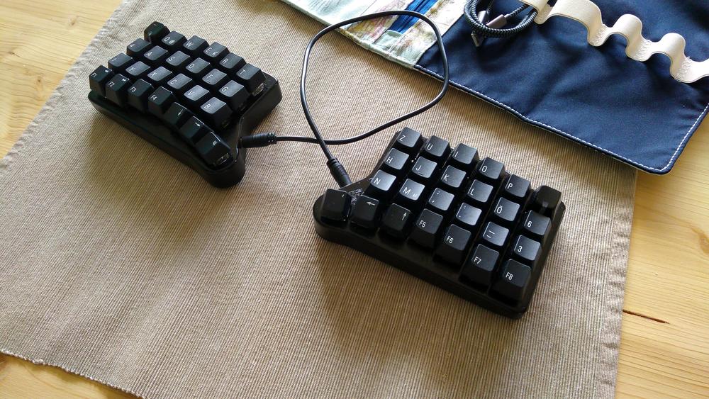
This is my pathetic attempt to show you how to build a split keyboard called "50one". It got all the good stuff like columnar stagger, a tiny bit of tenting, a couple of LEDs so you know which layer you are on, a small size perfect for taking it everywhere you go and two (hot swapable) Pro Micros running QMK firmware.
This is still a completely handwired build, so...
Be aware!
Handwiring this keyboard involves heavy use of soldering, wires, electronic components and tons of hot glue. It will lead to at least one burnt finger (otherwise you are doing it wrong).
If you have never built a keyboard or some other electronics before, this might be a challenging task. But don't leave jet: it is totally doable and I will personally hand out some medals afterwards.
(I actually wont...)
You might wanna have a look at this first...
There is a ton of information out there on how to build electronics and keyboards. I highly recommend reading up on the topics that are new to you, cause I won't be able to explain everything in full detail, so some background knowledge won't hurt.
Here, have some recommendations:
- QMK's handwiring guide
- Troy Fletcher - Handwiring a keyboard (videos)
- Hand-wiring a keyboard
- Brownfox build log
If you still have some questions, just leave me a message: max [at] mal-richtig.de
or you might find me on reddit at /u/maxmalrichtig.
"Dude, WTF?!"
Sorry for the poor quality of some of the images, the crappy 3D case and the (probably) bad English. If something is totally unclear, please let me know. If you have some better material, it would be nice if you could share it with the rest of us. :)
Build the build...
OK... You will need some stuff to do this.
First, print the case.
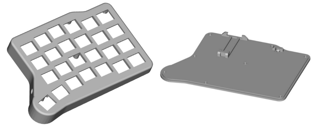
You will find the files needed to print the case with a 3D printer in this repository.
Download 50one_basePlate__V1.stl and the 50one_body__V1__CHERRY.stl
(if you are going to use Cherry-ish switches) or the 50one_body__V1__ALPS.stl
(if you are going with ALPS/MATIAS switches).
If you want to tinker with the 3D model or you want to build a better one, you can also have a look at the FreeCad project included.
Load the .stl files to your favorite slicer software (e.g. CURA)
and print the first half. In order to print the other half, you can
just mirror the 3D models directly in your slicer since the models are
completely symmetrical.
I printed my case with some generic PLA filament and a high layer resolution of ~0.1 mm. You don't want your print to be too crude or you'll have problems during further assembly.
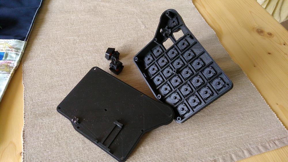
You should end up with a top & bottom part for the left and the right side.
Then, get some tools and components
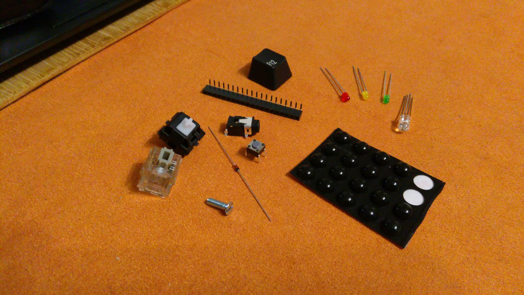
Components & parts:
- 2x Pro Micro
- 50x switches (Cherry, Matias, Alps, ...) of your choice
- 50x general purpose diodes (e.g. 1N4148)
- 16x M3 screws (6-10mm length)
- 2x 4.7k (through-hole) resistor
- 2x LUM 1503-13V - 4 pole TRRS jack 3.5mm
- 2x short-stroke switch (6x6 mm, height: 4.3 mm, vertical)
- also: keycaps and some non-slip rubber pads as feet
And yeah, don't forget the wires! I just used some generic, thin, stranded wire with several colors so I don't get too confused. The important thing is, that you have something flexible - so solid-core wires are no fun here (unless they are realllly thin). And better get some insulated wires, otherwise you will have to insulate the crosspoints between the wire (columns) and the diodes (rows) with hot glue, or something alike.
MODS - optional, but recommended:
hot-swapable Pro Micro: so you can change the Pro Micros after you have broken those delicate little micro-USB sockets
- 4x female pin headers, single row, 0.1" (2.54mm), right-angle, through-hole mount, (at least 11 pins long)
layer indication LEDs:
- 2x 5mm tricolor LEDs, 20 mA (L-154A4SURKQBDZG) - if you have clear switches like MATIAS
- 2x 200ohm resistors (for red)
- 4x 100ohm resistors (for green & blue)
- some heat-shrink (that fits over the resistors)
OR:
- 6x 3mm LEDs, 20mA, colors of your choice - if you have opague switches like standard cherry
- 6x some resistor
- some heat-shrink (that fits over the resistors)
(Since I can't know which LEDs you are using, I can't tell you which resistor values you will need. Google for "LED resistor calculator" if you don't know how to calculate the needed resistor or leave me a message! Do NOT connect the LEDs directly to the Pro Micro without a resistor in the circuit!)
Tools:
- screw driver (one that fits your M3 screws)
- hot glue and glue gun
- soldering iron and solder
- a small file (if you are going to use my 3D printed case - it needs some love for everything to fit)
- flush cutters
Insert the reset switches
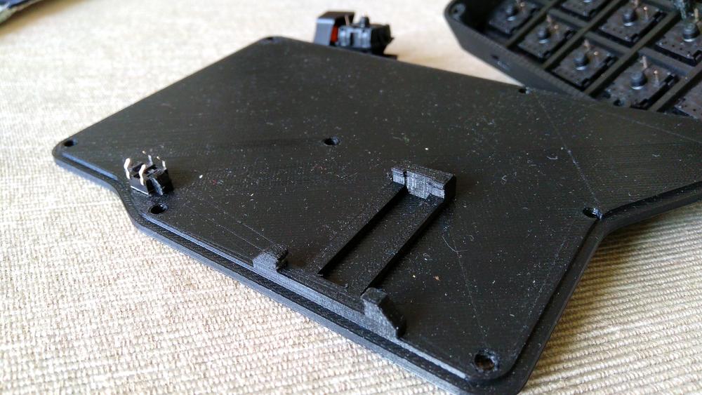
Take the bottom plates and the short-stroke switches and shove them into the little holder. If you have difficulties inserting the switch, take your file and file off some of the edges of the holder until you can place the switch.
After you have inserted the switch, it should be clickable by inserting a thin object through the hole on the other side of the bottom plate. (Please test!)
Insert your key switches
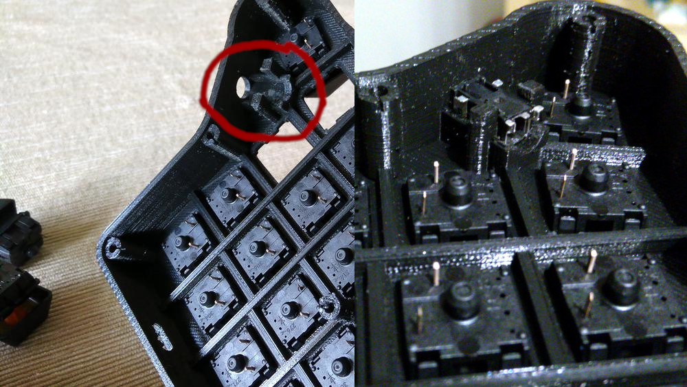
Now, take your favorite key switches and push them into the top part of the case. If you have problems inserting the switches, take your file and sand down the sides of the switch holes a bit until the switches fit nicely.
Make sure that all the switches sit flush on top of the case and there are no gaps or badly inserted switches.
Please note: Your switches might not lock in the switch plate, so they can be pulled out of the case pretty easy. This is "normal" - and one of the downsides of this 3D printed case. You can fix that with "some" drops of hot glue. (see the later images)
Insert the TRRS jacks
Take the TRRS jacks and insert them into the small holders on the inside of the case. Again, your file might be of good use here since the fit is quite snug.
The prongs on the TRRS jacks need to point "upwards" (away from the key switches) so you can easily solder some wires to them later.
Push it in hard - push it in good. You want the jack in there as plain as possible. If it still doesn't fit, go and use that file.
Wiring is the best part
This part can be extra fun - or you might wanna kill yourself afterwards. Maybe a little bit of both.
If we have all the switches in place, we can start building our rows and columns. Be careful while soldering to the switches: you want all your connections to be soldered as good as possible, so everything is connected well but be careful and don't overheat the switches with your iron. After all they are just plastic.
And for the record: The smoke from the rosin that is released during soldering is harmful, so be careful not to breath too much of it or get it in your eyes.
Give me some rows
We will build all the rows with the diodes. But since god is a funny man and he wanted to mess with all the people interested in electronics, he made diodes polar. That means, there is a "wrong way around" so pay attention that the marked end of the diode (the black part) is facing away from the pin of the switch you are soldering it to!
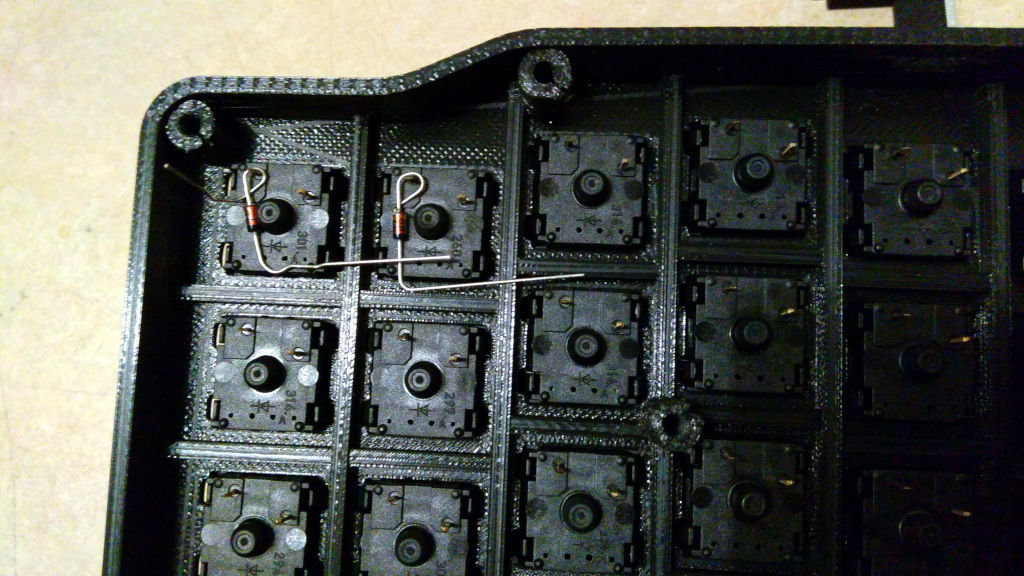
An easy way to solder the diodes is to bend the one lead in an angle or loop, put it over the pin of the switch and then apply some solder. Bend the lead on the marked end of the diode in a more or less right angle. Do the same for the switch next to that one an solder the diodes together where the two leads meet.
It should look more or less like this (just without the wires in the picture - sorry, I forgot to take a picture that is just showing the rows...):
After you have finished a row with the diodes, take one of your wires and solder it to last diode. We will use these wires later to connect them to the Pro Micros, so make sure they are long enough to reach the Pro Micro. Better make the wires a little bit too long than too short!
Do this for every row of switches on either side.
Columns for the win
The idea behind this step is to connect all the unused pins of your switches in a column to each other. There are several ways to do this and it doesn't matter which one you choose. But here is the way I did it:
Take one of your wires and solder it to a switch on the bottom. Pull the wire up to the next switch, put some solder on the tip of your iron and hold it against the wire at the position where you want to connect it to the next switch. Don't touch the pin of the switch yet - just melt away the insulation of the wire at that point. Now put some more solder on your iron and solder that point of the wire to the pin of the switch. Incrementally apply more solder to the joint until point of total satisfaction is reached.
Pull the wire up to the next switch and redo this procedure until you have soldered every switch in this column. Do NOT cut the excess wire - we will use that to solder the columns to the Pro Micro later on.
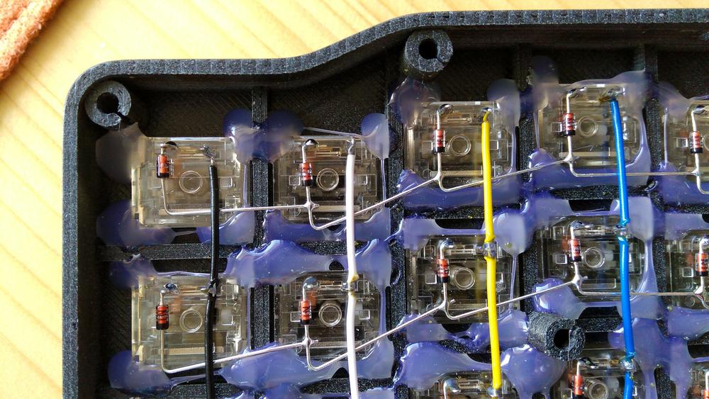
Do this for every column of switches on either side.
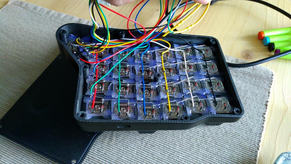
After you are finished with the rows and columns, you should end up with something similar like this:
Put in the Pro Micros and make 'em reset
Wire the Jacks
|---|
o   o <--- 5V / VCC  (eiter of both pins can be used)
|   |
o-o-o <--- SDA / Pin 2
  ^------- GND
^--------- SCL / Pin 3
